


This presents a conceptual Internet architecture designed as a Software Architecture, reimagining the Internet from scratch as if it were the 1970s. It outlines the system’s core requirements (reliability, scalability, interoperability, availability, and security), defines a hierarchical network model (Users, Navigators, Regionals, and Continental Anchors), and explains how discovery, routing, packet structure, failover, traffic prioritization, and security work together. The goal is not to replicate today’s Internet, but to demonstrate structured architectural thinking and end-to-end design reasoning.
1. Definition #
The Internet is a decentralized global network of connected computer nodes and devices that communicate with each other through standardized communication protocols.
Rather than relying on a single central hub, it operates a massive “network of networks” that can link both private and public networks together, allowing seamless data exchange between any parties.
2. Requirements #
- Availability - Ensure that is reachable by any user, from any location at any time.
- Reliability - Implement fail-safe mechanisms that prevent data loss or service outage during crashes or errors.
- Interoperability - Enable communication across different types of devices (hardware, operating systems, local networks, etc.).
- Scalability - Maintain performance while handling continuous growth in demand and, for example, in the number of users.
- Security - Protect the integrity and privacy of user data against malicious attack or unauthorized access, so that users trust that they are safe while using the internet.
3. Architecture of the internet #
The internet operates as a tiered, decentralized network designed for global reach and local resilience, as shown in figure 1, which illustrates this topology, mapping the flow of data from massive intercontinental hubs down to individual end-users.
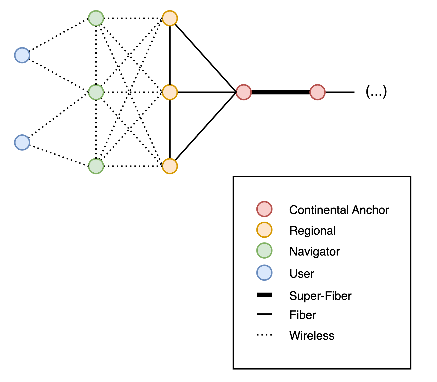
Figure 1: Internet Topology and Hierarchy
3.1. Components of the Internet #
The network relies on a distinct hierarchy of nodes that range from continental anchors to personal devices which work together to route data efficiently and maintain stability, even upon local hardware fails. These hierarchical components can be described as follows:
Continental Anchor:
- These are centers responsible for intercontinental data exchange as fast as possible.
- It is possible to add more anchors as the internet user grows.
Regional:
- These are signal towers distributed throughout the cities that serve as the bridge between the global cables and the local users.
- If a Regional loses its connection to the Continental Anchor, it sends to the neighbouring Regional instead.
Navigator:
- These are the smart devices in the user’s home or any location that finds the best path for the transferred data (router 2.0).
- If a navigator loses its signal to the Regional, it automatically “hops” the data to a neighbouring Navigator to stay on.
User:
- These are the user devices, such as phones, computers, laptops, etc.
- They represent the start and end point of all communications.
- Users can connect to any nearby Navigator.
3.2. Connections between the Components #
To link these nodes, the system utilizes a tiered network of physical and wireless pathways, which scale in both capacity and cost:
Super-Fiber:
- Connection between Continental Anchors that acts as “super-highways” for the data.
- Hard material distributed under the oceans designed to be unbreakable and to carry heavy worldwide data traffic.
Fiber:
- Connection between Regionals / between Regional and Continental Anchor that acts as “main streets”.
- It is the same as super-fiber, but cheaper and mostly underground.
Wireless:
- Connection between Navigators / between Navigator and Regional / between User and Navigator that acts as the “last kilometer”
- It uses radio waves, in order to allow users to connect to the internet without connecting a cable to their device.
3.3. Node Information #
For the network to function properly, each component must store specific information about itself, its neighbors, and its current state. The data each component maintains is shown below:
User:
- Own permanent ID (global unique ID 256 bits);
- Own address (with the primary Navigator);
- Navigators list (for failover);
- Packets waiting queue (for priority).
Navigator:
- Own permanent ID (global unique ID 256 bits);
- Own address (with the primary Register);
- Regionals list (for failover);
- Hop count;
- Neighbour Table;
- Routing Table (local mesh + routes to Regionals);
- Connected Users list;
- Packets waiting queue (for priority).
Regional:
- Own permanent ID (32 bits);
- Own address;
- List of connected Navigators;
- Packets waiting queue (for priority).
Continental Anchor:
- Own permanent ID (16 bits);
- Intercontinental routing table;
- List of connected Regionals;
- Packets waiting queue (for priority).
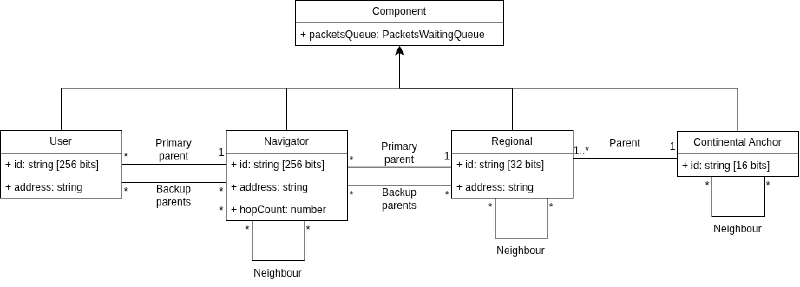
Figure 2: Diagram of the internet components
3.4. Discovery #
For a device to participate in the network, it needs two things: an address to identify itself, and knowledge of its neighbors to know where to send packets. The discovery process handles both of these needs when a new component joins.
3.4.1. Addressing Scheme #
To ensure data packets reliably reach their destination, every entity on the network is assigned a unique, hierarchical address. This structure promotes scalability by allowing routers to focus on broad geographic regions rather than maintaining a map of every individual user.
If the new component is a User or a Navigator, their IDs are unique (256-bits UUID) and will be randomly attributed and if it is a Regional, the Anchor is able to attribute its ID.
Address format:
[Anchor ID].[Regional ID].[Navigator ID].[User ID]
EXAMPLE
Simplifying, 3.12.4.40 means:
- Anchor 3
- Regional 12
- Navigator 4
- User 40
3.4.2. Discovery Process #
For the network to work, every device needs to know who is nearby. This happens through a simple “shout and listen” process:
- How a User joins: When a device turns on, it “shouts” a signal to the area. Any Navigator that hears it will reply. The User then knows exactly which Navigator to use to send data.
- How a Navigator joins: Navigators also shout to their surroundings. They listen for replies from other Navigators or nearby Regionals.
- Building the List: Every time a device gets a reply, it adds that neighbor to its Neighbor Table. This table is like a local contact list that tells the device who is close enough to talk to.
If a Navigator moves or turns off, the neighbors are able to notice it, so they simply update their list and find a new path. It finds the fastest path by talking to neighbors, a Navigator can figure out which one is the “closest” to any Regional by counting the “hops” – if the Navigator:
- has a direct link to Regional, Hop Count = 1;
- has not been directly linked, Hop Count = min(neighbour hops) + 1.
The nodes will recursively define the Hop counts of each Navigator, starting with the ones that are directly connected to a Regional.
3.5. Data Routing #
Once a device has an identity and neighbors, it must be able to send data across the world. It works by “climbing” from the local neighborhood up to the global core and back down again
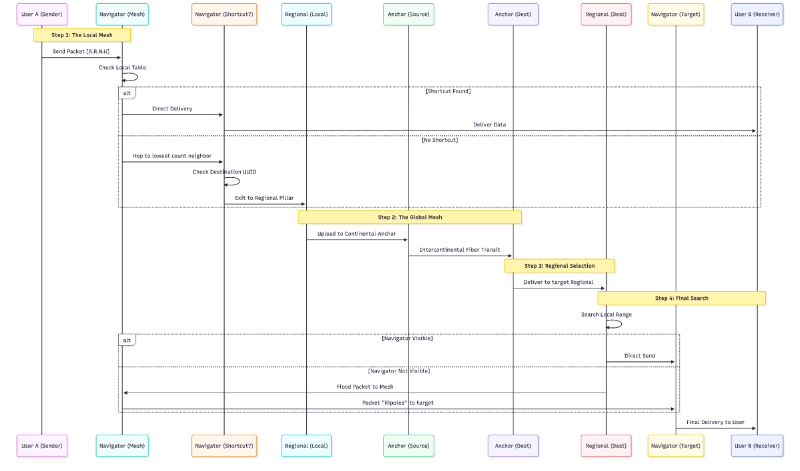
Figure 3: Data packet transit flow
A packet begins its trip by “climbing” out of the local wireless mesh. It doesn’t need to find a specific Regional, only the nearest Regional to access the super-fiber network. It does this by always hopping to the neighbour with the lowest Hop Count until it reaches the first available exit.
Once on the global fiber network, the packet is routed based on its Anchor ID. It travels across intercontinental cables until it reaches the correct Continental Anchor. From there, the target Continental Anchor passes it down to the destination Regional, either directly or through a regional fiber mesh.
Finally, the process reverses: the destination Regional performs a local search. If the target Navigator isn’t immediately visible, the Pillar floods the packet into the mesh. The data “ripples” through the neighbourhood until the specific Navigator recognizes its ID and delivers the data to the final user.
The Local Shortcut: While the packet is “climbing” toward the Regional, every Navigator it passes checks the destination ID. If a Navigator recognizes the Navigator UUID or the User UUID as someone in its own local list, it takes a shortcut. It delivers the data directly to them, skipping the Regional and Anchor entirely. This keeps local traffic efficiently and reduces the load on the global network.
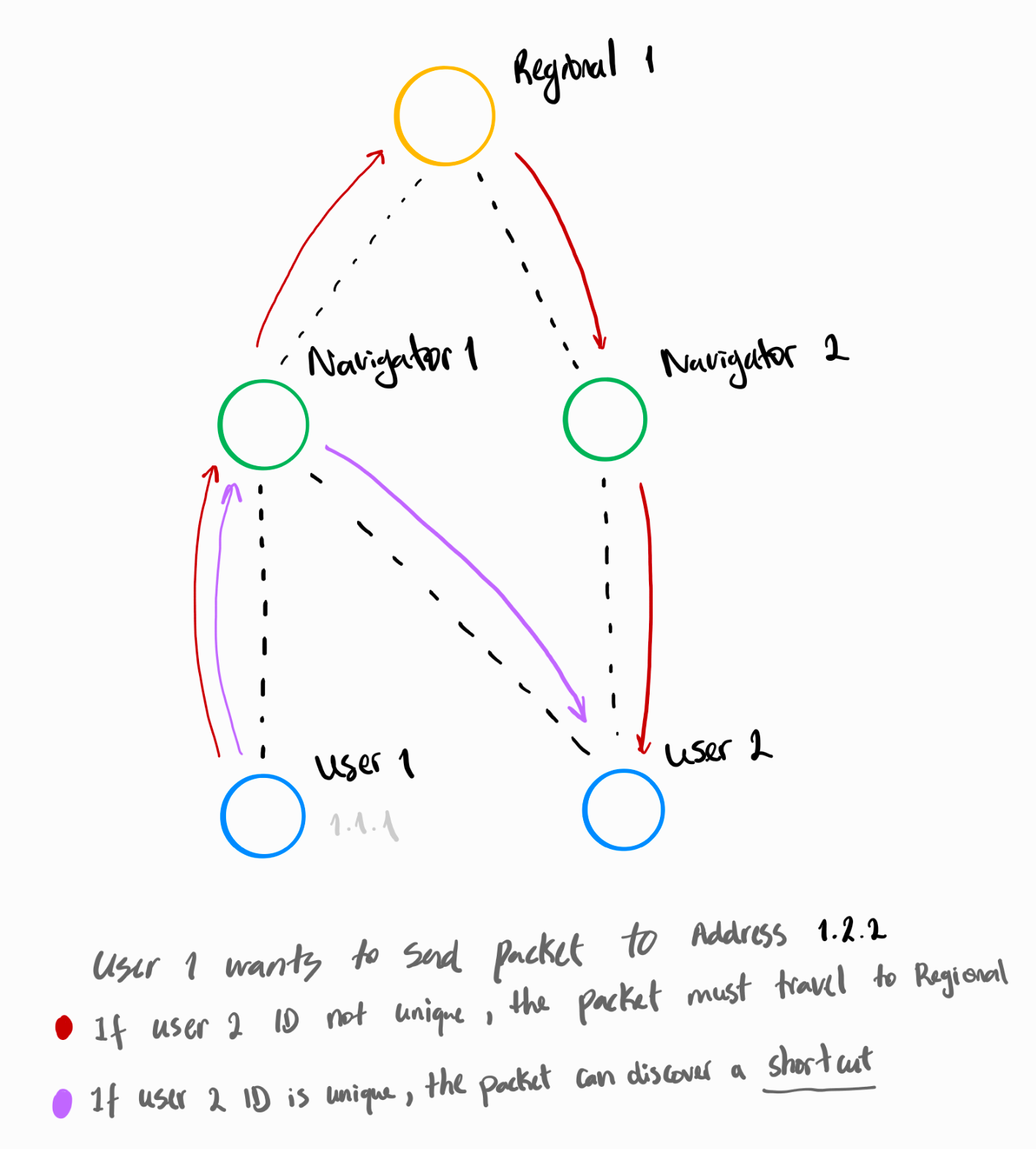
Figure 4: The reason to use Unique IDs on Users (but also on Navigators) to enable shortcuts
EXAMPLE
Sender: Anchor 1, Regional 5, Navigator 7, User 10.
Receiver: Anchor 3, Regional 12, Navigator 4, User 40.
Step 1: The Local Mesh:
- User 10 sends the data packet to Navigator 7
- Navigator 7 verifies the destination is not within its wireless range
- It identifies the neighbour in its Neighbour Table with the lowest Hop Count
- The packet “hops” through the mesh until it hits the first available Regional
Step 2: The Global Mesh
- The Regional receives the packet and checks the destination Anchor ID (3)
- If Anchor 3 is not its direct parent, it passes the packet to its linked Continental Anchor
- The Anchor checks for a direct path to Anchor 3
- If the path is not listed, it sends the packet to every physically linked Anchor until it reaches Anchor 3
Step 3: Regional Selection
- Anchor 3 receives the packet and identifies the target Regional 12
- It attempts to send the packet through its direct link to Regional 12
- If not directly linked, it sends the packet to all physically linked Regionals, until it reaches Regional 12
Step 4: Final search
- Regional 12 receives the packet and checks for Navigator 4 in its immediate wireless range
- If Navigator 4 is not visible, it floods the packet to all Navigators in its local mesh
- Each Navigator checks the ID; if it is not the target, they broadcast it to their own neighbours.
- Navigator 4 recognizes the destination ID and delivers the data to User 40.
3.6. Data Packets #
To ensure that any type of device can access the Internet and communicate with others, we must adopt a common, standardized data packet format. For this model we have:
- Link Header: used only for delivery between two directly connected devices (User ↔ Navigator, Navigator ↔ Regional)
- Network Header: this is the global routing protocol, using our [Anchor].[Regional].[Navigator].[User]
- Control Header: simple reliable mechanism
- Payload: the actual content that we are sending, such as a data chunk with binary bytes (can be messages, videos etc.)
EXAMPLE
For the Link Header:
| Field | Value | Purpose |
|---|---|---|
| Destination Component ID | 5.12.4 | Next Hop ID |
| Source Component ID | 5.12.7 | Sender ID |
| Link Type | Wireless | Fiber / SuperFiber / Wireless |
| Hop Count | 3 | Remaining hops to regional |
For the Network Header:
| Field | Value | Purpose |
|---|---|---|
| Source address | 1.5.7.10 | Full hierarchical address |
| Destination Address | 3.12.4.40 | Full hierarchical address |
| Packet ID | 88421 | Unique ID for retransmission |
| TTL | 20 | Prevent infinite loops |
| Priority Level | 2 | Used for traffic priorization |
| Checksum | 0x93AF | Header integrity |
For the Control Header:
| Field | Value | Purpose |
|---|---|---|
| Sequence Number | 1001 | Order control |
| Acknowledgement Number | 1000 | Confirm previous receipt |
| Retransmission Flag | 0/1 | Indicates resend |
| Window Size | 500 bytes | Flow control |
| Integrity Code | Parity / Checksum | Detect corruption |
3.7. Reliability and Fault Tolerance #
As discussed above, each User and Navigator has a global unique ID, and they can have multiple connected parents, being one of them the primary. By using this implementation, the network becomes resilient against failures.
When a primary parent fails, its child can temporarily send packets through another available parent in their parents list (“Navigators list” for Users and “Regionals list” for Navigators). This failover mechanism works differently for Users/Navigators compared to Regionals/Anchors, as only the lower tiers maintain parent lists for redundancy.
EXAMPLE: How failover works for Users?
User 1 is normally connected to primary Navigator 20. It also keeps Navigator 30 in its Navigators list as a backup. If Navigator 30 fails:
- User 1 detects loss of connection to its primary Navigator;
- It immediately connects to backup Navigator 30;
- User sends a location update: “I am 1, no connected through 30”;
- 30 adds 1 to its connected Users list;
- The network updates its location records;
- All future packets for 1 are routed through 30.
Throughout this process, User 1’s ID and address never change.
3.8. Prioritize Traffic #
In a network with millions of users, “traffic jams” are inevitable. To keep the network Reliable and Available, we use a Priority System. Every packet has a “Priority Level”, and every node (Navigator, Regional, and Anchor) processes these packets based on their importance.
All nodes process lower numbers first, using a queue. If a Navigator receives an “Emergency” packet and a “Normal data” packet at the same time, it sends the Emergency data immediately and makes the Bulk data wait in a buffer.
The priority of a packet is not fixed by one person, but rather assigned based on the nature of the application and the state of the network.
| Priority | Meaning |
|---|---|
| 0 | Emergency |
| 1 | Real-time communication |
| 2 | Normal data |
| 3 | Background / bulk transfer |
3.9. Security #
A network is considered secure if it remains reliable after failures or attacks, if the receiver is able to determine the origin of the data, if the data isn’t altered while it is being transmitted and if someone who did not receive or send the message cannot access it.
To ensure these points we rely on different security protocols to protect data in networks that aren’t always secure. These protocols use cryptography to keep information private, confirm the sender’s identity and make sure it wasn’t modified while it was being transmitted, encryption makes the data unreadable so that it cannot be read without a key, while public and private keys enable secure communication, even if we haven’t shared a secret key before. Digital signatures help verify the sender’s identity and detect any changes to the data, and key exchange lets us safely agree on a shared key so encryption can happen efficiently.
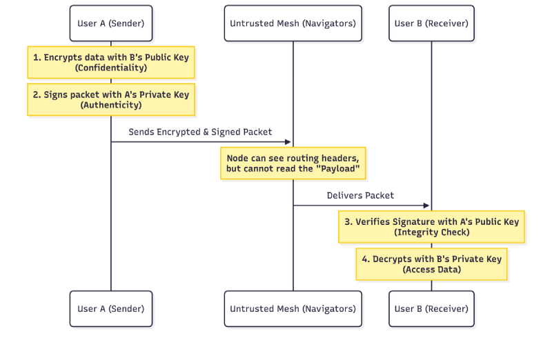
Figure 5: Security end-to-end communication diagram